Circuit-breaker switch: purpose, principle of operation, wiring diagram
For the organization of backup power in privatehouses and enterprises install generators. This is caused by the need, especially in the winter, to have uninterrupted power supply, since most modern heating systems are equipped with electronics, without which they do not function.

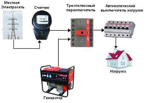
The generators are switched by connecting them in parallel to the central power line through a special switch, which excludes parallel connection.
Thumbwheel switch: operating principle
An electrical type device that servesdisconnecting the electrical load with one power source and connecting it to another source, is called a toggle switch, or a change-over switch (with a mid-point switch). Devices come with or without arc chokes. In the first case, switching networks can occur with a fully connected load. In the second - only when it is turned off.

The operation of the switch is done manually, thenthere is, if necessary, to switch sources of power supply, the operator acts on the isolated control lever of the switch. There are also automatic switching systems.
Circuit-breaker circuit
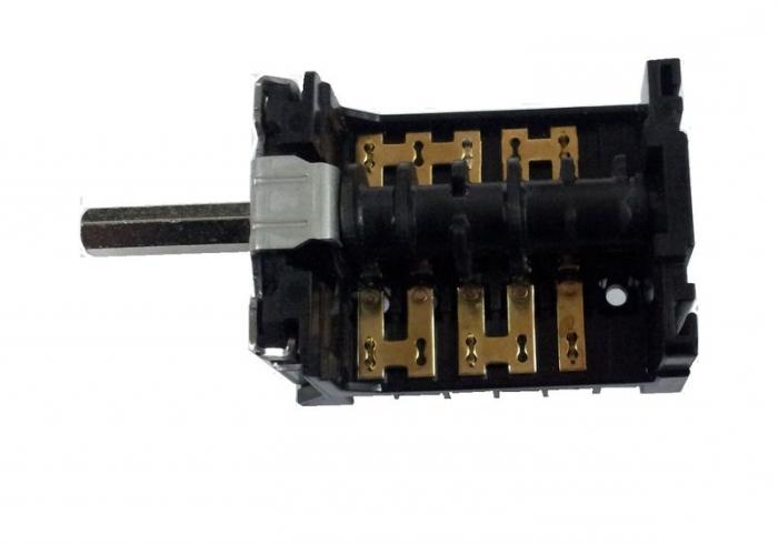
The toggle switch consists of a housing,movable knife-type contacts fixed to the shaft, fixed contacts, control knob, arc chute (if any) and terminals for connection to the line. The device has two working positions (pins 1 and 2) and one neutral (intermediate), in which no load is connected to any of the lines.
A simple scheme for switching on two power sourcesand one load line looks like this: to contacts 1, for example, the central power supply is connected, to contacts 2 - diesel or another kind of electric generator. The most common are four-pole switches and two-pole switches.

Connection of the circuit-breaker in the case of entering three-phase voltage into the building is as follows:
- the switch must be at four poles;
- four terminals go to the network input;
- four terminals go to the generator input;
- A load is connected to the four terminals.
Three of the four terminals go into phases, one to zero.
Characteristics
The main characteristics of the switch are:
- The rated current that it can flow. Devices are produced on 15.0, 25.0, 32.0, 40.0, 63.0, 80.0, 100.0 and 125.0 A.
- Thermal current, not destroying the elements.
- Allowable mains voltage.
- Short-time impulse voltage, which can withstand insulation.
- The number of poles that can simultaneously switch a changeover switch.
- The wear resistance of electrical contacts is determined by the operating voltage and the amount of current passed.
- The wear resistance of mechanical elements is determined by the number of switching cycles.
Modifications of change-over switches
Two-way knife switches are used to work insingle-phase circuits. Such switches are provided with capacitors of a through type. There are two- and three-module versions. In combination with a switch-over switch, a power supply unit designed for a voltage of up to 300 volts can operate. A switch is installed in the switchboards of various types. When used with a generator, the permissible voltage must not exceed 350 volts. For the load, the average current transmittance is 30 amperes.

Three-way knife switches have a design,based on the expansion switches. Most often they are used for circuits of two-phase type and installed in industrial plants. Switches of this type can have blockers. As a rule, three-way switches have a high threshold of sensitivity. Also, the devices are equipped with a protection system.
Circuit breaker type
All of the above change-over switcheshave one drawback - require the presence of a person for manipulating circuit switching. This is inconvenient, especially when the central power supply is often lost and unpredictable. Therefore, a change-over circuit breaker has been developed. More precisely, this is a whole block, called automatic input of reserve (AVR).
ATS is a complex construction, but folkcraftsmen collect such systems from relatively inexpensive relay devices (contactors). Apply for this model with normally closed and open contacts.

When using a self-made flip-flopswitch, the wiring diagram operates according to a certain principle. For example, in the line there is central supply electricity, then the relay with normally open contacts closes the circuit with the load. The relay with normally closed contacts, where the generator is connected, in this case is open. As soon as the current disappears, the combination changes to the opposite, and the network begins to power the generator.
Conclusion
Application of breakers for switchinggenerator represents an expedient solution that allows to have significant advantages. In addition to facilitating the maintenance of an individual power source, this device makes it possible to keep under control the functioning of the network and ensure the safety of all elements included in the line. To select the best option for the change-over switch, first of all, they are guided by the individual features of the electrical network and the devices included in it. Proceeding from this, a switch is selected with a change-over switch with characteristics that satisfy such requirements.
</ p>


