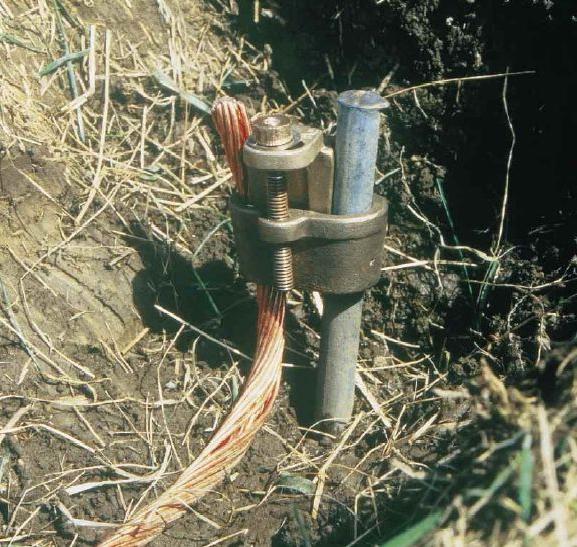
Basic grounding systems
A person unfamiliar with electrical engineering may think that in all residential buildings the same schemes of power distribution are used: the same two wires, switches and sockets.

Currently widespreadreceived three main grounding systems - IT, TN, TT, and their derivatives. This symbol is quite informative, but only if you know how to decipher it.
Existing earthing systems
This definition indicates one or the otherthe configuration of the existing electrical network, taking into account the earthing option of the equipment used by the end user, how the ground wire and the zero line are switched on, and whether the neutral is grounded. That is, this concept is generalizing. Depending on the combination of these moments, three classes are distinguished.

Its logical development is TN-C. Here, "C" means "combined". The difference from the previous one is that the neutral wire and the grounding wire are united in a single line. This feature allows you to reduce the number of lines laid, but when this wire breaks off on the enclosures of the devices included in the network, an electrical potential appears, which is dangerous. However, sometimes this method is used by craftsmen in the absence of a third grounding wire in the apartment: in the sockets between zero, and a grounding jumper is placed. Such systems of grounding are recommended to be used in two cases:
- there is no other way to ground the equipment;
- the line is additionally protected by a residual current circuit breaker.

The next main system is TT. Structurally there are two independent grounding lines: one is located on the transformer side, and the other is on the consumer side.
Finally, one of the most reliable optionsIt is represented by the IT system, in which the neutral lines are made isolated, and all cases of the consumer devices are reliably grounded. As a result, the natural leakage current is extremely insignificant and even when the person accidentally hits the electric potential does not present a danger, leaving to the ground. In this case, it is important to control the resistance value.
Any system must be respectedThe rule that grounding resistance can not exceed 4 ohms. Therefore, any system, starting from grounding pins and ending with conductors and connection points, is checked for compliance with this requirement.
</ p>


