How to make an oscilloscope from a computer?
The oscilloscope is one of the key instruments,as for any industrial radio laboratory, and a conventional radio workshop. With the help of such a device, it is possible to determine the malfunctions of electronic circuits, and also to debug their work when designing new devices. However, the price of such devices is very high, and not every radio amateur can afford to buy such a thing. This article is devoted to the question of how to make an oscilloscope from a computer. There are many ways of making such a device, but the basis is everywhere the same: a PC sound card serves as the board that will receive pulses, and a special adapter is attached to it. It serves to match the levels of the measured signals and the input of the computer's audio card.

Oscilloscope on a computer: software
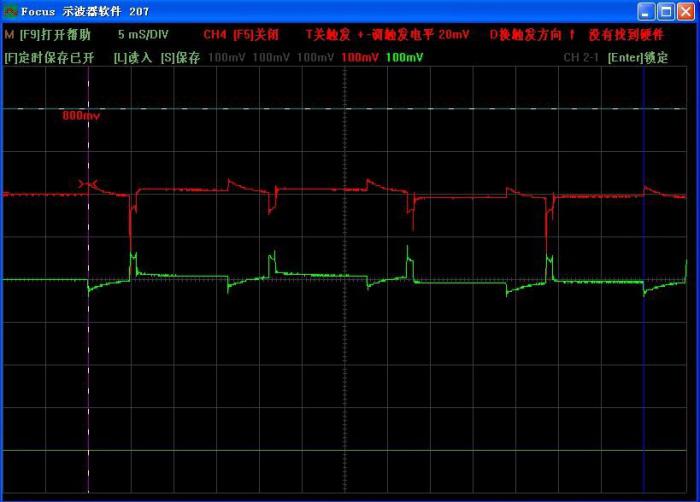
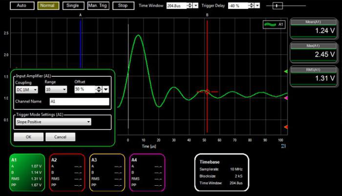
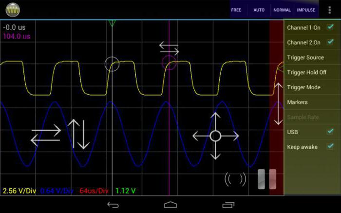
One of the main elements of the deviceis a program that on the monitor produces visualization of measured pulses. There is a huge selection of such software, but not all utilities work stably. Especially popular with radio amateurs is the Osci program, from AudioTester. It has an interface that looks like a standard analog device, there is a grid on the screen that will allow you to measure the duration and amplitude of the signal. It is convenient in operation, and has a number of additional functions that are not available for programs of this type. But each ham will be able to choose the software for work that he likes.

Technical data
So, in order to make an oscilloscope fromcomputer, it is necessary to assemble a special attenuator (voltage divider) that can cover the widest possible range of the measured voltage. The second function of such an adapter is to protect the input port of the sound card from damage that can cause a high level of voltage. For most audio cards, the input voltage is limited to 1-2 volts. The oscilloscope from the computer has a frequency range limited by the capabilities of the sound card. For budget cards it is from 0.1Hz to 20kHz (sinusoidal signal). The lower limit of the voltage that can be measured is limited by the background and noise level and is 1 mV, and the upper limit is limited by the parameters of the adapter and can be several hundred volts.
Device of the voltage divider
The oscilloscope from a computer differs verysimple electrical circuit. It contains only two zener diodes and three resistors. The nominal value of the resistors depends on the virtual oscilloscope scale used. This divisor is designed for three different scales, with coefficients 1: 1, 1:20 and 1: 100. Accordingly, the device will have three inputs, to each of which a resistor is connected. The nominal resistance of the direct-current resistor is 1 MΩ. The common wire is connected via a reverse connection of two zener diodes. They are designed to protect the line input of the sound card from overvoltage when the switch is in the "direct input" position. In parallel resistors can connect capacitors, they will equalize the amplitude-frequency component of the device.

Conclusion
Such a computer oscilloscope is not differentelegance, but a simple circuit solution will achieve a wide range of measured voltage. This device will help in the repair of audio equipment or can be used as an educational measuring device.
</ p>


