T-trigger. Principle of operation, functional diagrams
Trigger is the simplest device that representsdigital automatic machine. It has two states of stability. One of these states is assigned the value "1", and the other "0". The state of the device, as well as the value of the binary information stored in it, is determined by the output signals: direct and inverse. In the case when a potential is established on the forward output, which corresponds to a logical unit, in such a case the trigger state is called single (the potential on the inverse output corresponds to a logical zero). If there is no potential on the direct output, then the state of the trigger is called zero.
Classify the triggers in the following ways:
1. By the method of the recorded information (asynchronous and synchronous).
2. By the method of information management (statistical, dynamic, single-stage, multi-stage).
3. By the way of realization of logical connections (JK-flip-flop, RS-flip-flops, T-flip-flop, D-flip-flop and other types).
The main parameters of all types of triggers are: the maximum duration of the input signal, the time delay required for switching the trigger, and also allowing the response time.
In this article, let's talk about this type of device,as - T-trigger. Such triggers have only one information (T) input, which is called a countable input. It changes its state and state after receiving the counting (T) input of each control signal.
According to the transition table, the lawThe function of such triggers is described by the characteristic equation: Q (t + 1) = TtQ "t VT'tQt. From the equation it follows that when a logic zero arrives at the input (T), the T- will reverse.
| Qt | Tt | Q(t + 1) |
| 0 | 0 | 0 |
| 0 | 1 | 1 |
| 1 | 0 | 1 |
| 1 | 1 | 0 |
It can be seen from the table that the T-flip-flop performsaddition operation, this is what caused the name of such a trigger to be countable, its information (T) input is a countable input. The signal level at the input of such a trigger appears twice as often as at its output (Q). Accordingly, the T-flip-flop is used as a frequency divider.
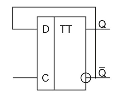
A T-trigger of an asynchronous type can beis constructed on the basis of a two-stage RS flip-flop with additional connections, namely: the output of the flip-flop (Q) must be connected to the input (R), and the output (Q ') to the input (S). The information input (T) will be the synchronous input (C).
The photo shows a T-trigger. Functional scheme.

In the initial state at the information inputs(R and S), a logical zero level is applied, when a logical zero is input to the counting (T) input, the state of the first trigger will be copied permanently by the second trigger, because the NAND item will output the logical unit level to the input of the second flip-flop. If the T-flip-flop is in the state of unity, then the inputs (R and S) will be fed with zero and unity levels, respectively. When the first signal arrives at the counting input equal to the logical one, the logical unit is written into the first trigger. The state of the second trigger does not change, because the zero level from the output of the AND gate does not block its state. After the counting pulse is removed, the input (T) is set to zero, and the second trigger switches to the logical one.
In the photo there is a synchronous T-trigger. Functional scheme.

Synchronous T-flip-flops are used if necessary to represent the potential of a logical unit sequence at the input of the T flip-flop.
</ p>